



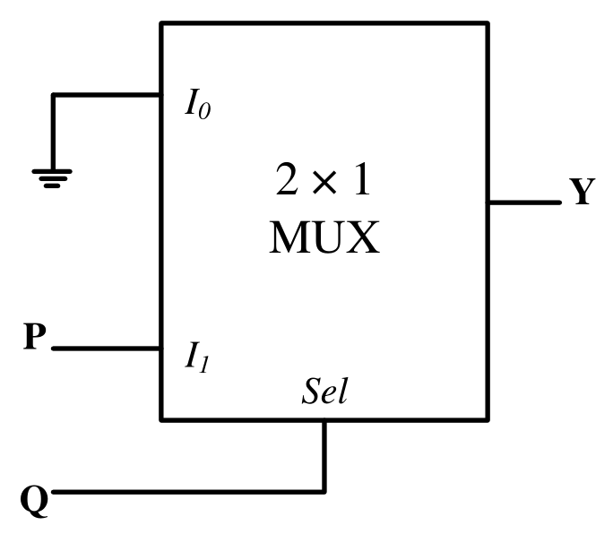
In the circuit shown below, P and Q are the inputs. The logical function realized by the circuit shown below is
- A
- B
- C
- D
Combinatorial circuitslogic gates and their static CMOS implementationsMCQ1 mark · −1/3 if wrongMedium
A GATE question every morning
One real past-paper question every morning for your branch, answer hidden until you tap. Free on Telegram.