



Consider the boost converter circuit shown. Assume that the semiconductor devices are ideal. In steady state, the inductor current rises linearly from 0 A to 6 A in the first 10 μs and then falls linearly from 6 A to 0 A in the next 10 μs of every switching cycle as shown. The load resistance is 10 Ω and the capacitance is 500 μF.
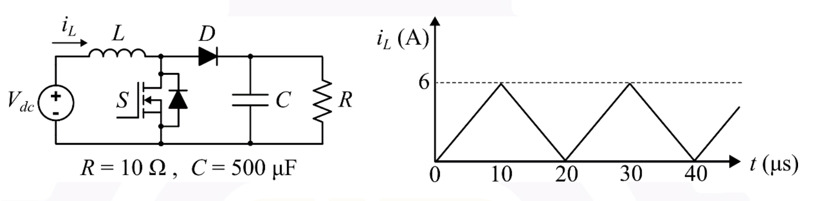 Neglect the ripple in the output voltage. What is the input voltage ?
- A10.0 V
- B15.0 V
- C7.5 V
- D12.5 V